 By: Admin
How RISA-3D Calculates Member Deflection Ratios
After solving a model, you will see in the Member Deflections spreadsheet the following deflection ratios:

Try the Complete RISA Suite for
10 Days FREE

RISA Education

Video Library

Online Help

Get Support

About Us
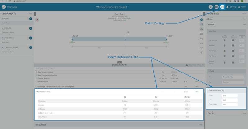
RISA-3D v16.0.4 introduces an enhancement that will allow for more control over the beam deflection ratio through Deflection Ratio Options. As part of the member properties, you can now designate the ends of single and multi-span beams as a cantilever or supported. This will determine whether the beam deflection ratio is calculated as L’/y’ (supported) or 2L’/y’ (cantilever).
From the Members spreadsheet, go to the Advanced tab, where you can designate the Defl Ratio Options.
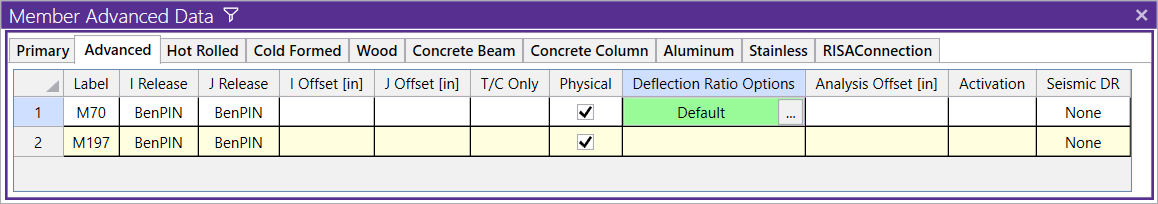
Note: These options are only applicable to members designated as beams. By default, the deflection ratio will be calculated automatically, either as a supported member or as a cantilever.
An example of when the deflection ratio option can be useful is if the beam deflection ratio of a member is calculated by the program as a cantilever, but you consider it to actually be supported. You can then set the deflection ratio options to explicitly specify that it is supported and the beam deflection ratio will be adjusted accordingly.
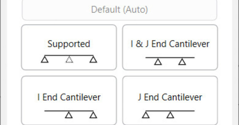
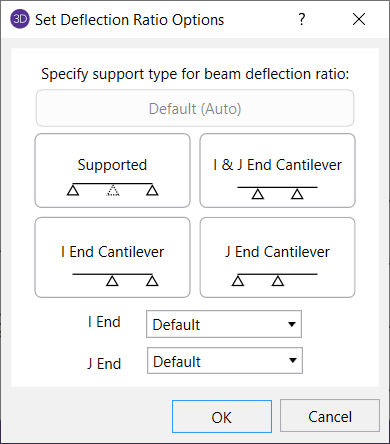
Single span beams can be designated as supported on both ends, or cantilevered from either end. In addition, multi-span beams have the option to be designated as a double cantilever, where both ends are free.
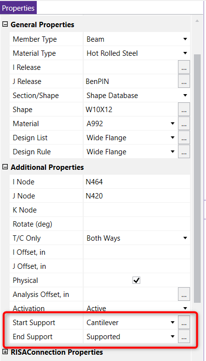
You can also click on the member to open up the Member Properties and set the deflection ratio options in the Additional Properties section.
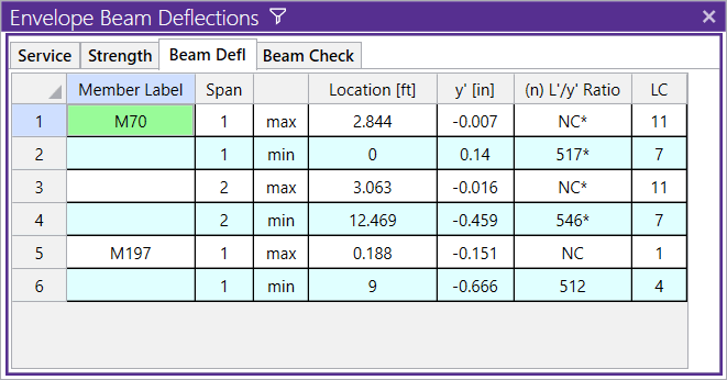
As you view the beam deflection results in the Beam Defl tab of the Member Deflections spreadsheet, all the ratios that were modified by setting the deflection ratio options will be denoted with an asterisk suffix. The reported location will correspond with the location of maximum relative deflection.
Using the deflection ratio options will not change any global deflection, and is primarily used when designing members based on allowable deflection ratios.
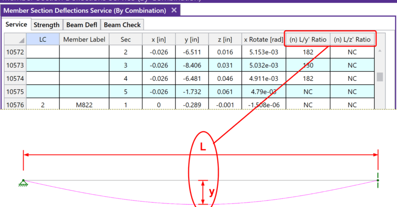
After solving a model, you will see in the Member Deflections spreadsheet the following deflection ratios:
As our team is hard at work updating and improving RISACalc based on customer feedback and requests. This latest release (Version 2.1) now...
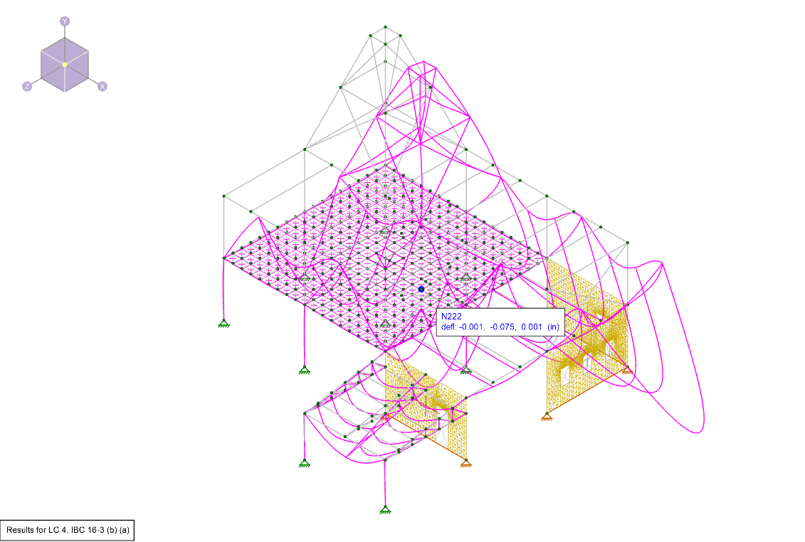
Deflection is a key tool for verifying whether your model was built correctly in RISA-3D. After solving, you can view the deflected shape to...