Understanding Plate and Member Interaction in RISA
When modeling plate elements alongside member elements in RISA, users may notice that member forces—such as bending moments or axial loads—are lower...

Try the Complete RISA Suite for
10 Days FREE

RISA Education

Video Library

Online Help

Get Support

About Us
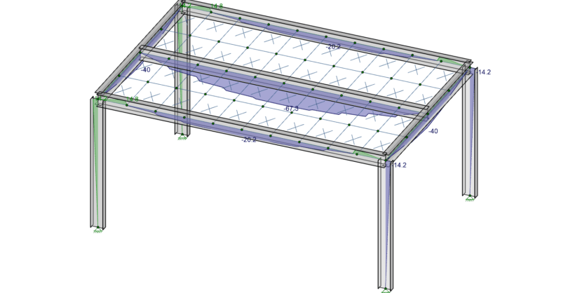
In order to understand the interaction between plates and members it is important that you know the basics of Physical Members and Plate Connectivity. Remember that plates only connect to other elements at their corners, and you will instantly recognize why the model below will not work as intended.
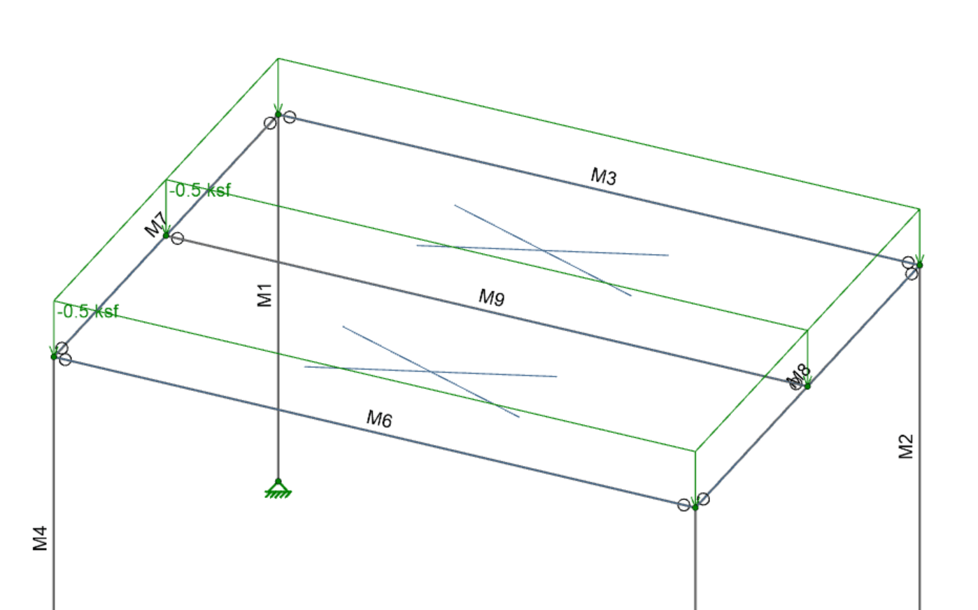
In this model there are two plates, defined between members M2, M5, and M9. The moment in all three beams is zero though, because the surface load on the plates goes to their corners, which fall only on the girders and the columns. In order to get a more realistic one-way load distribution to the beams the plates actually need to connect to them (since plates do not connect to anything along their edges).
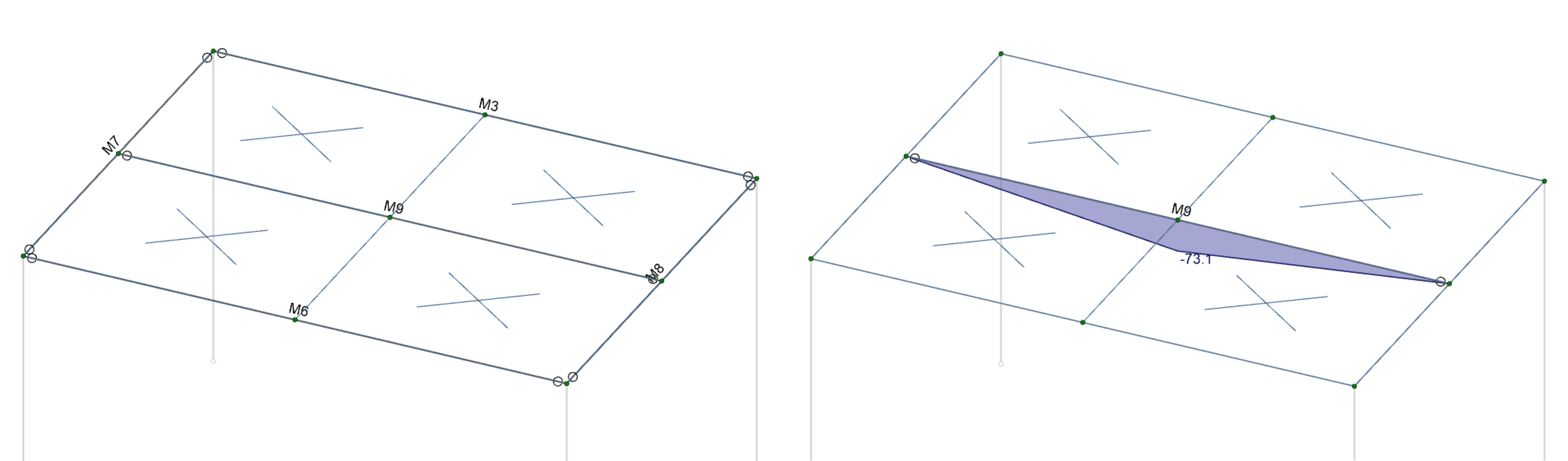
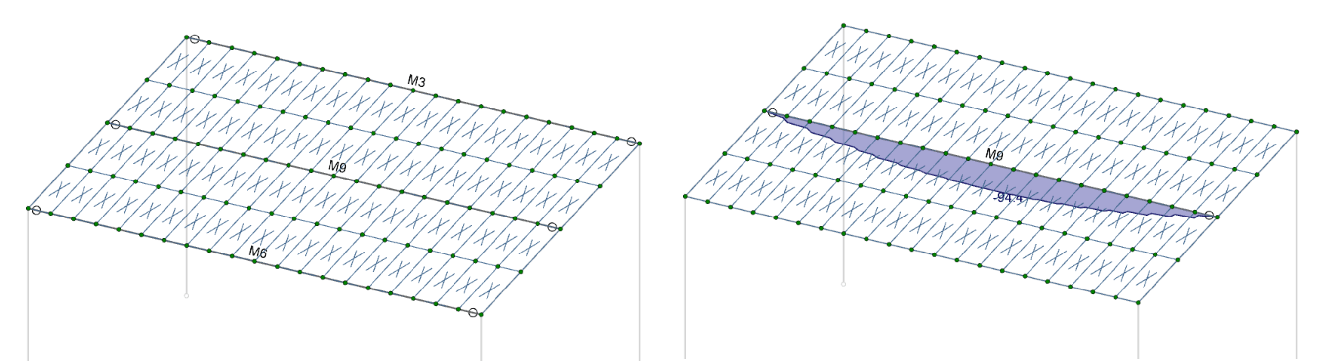
Above is a submeshed model. The moment diagram for member M9 is plotted on the right. As you can see, the plates are only connected to that member at its midspan, so it is being loaded with a single point load right in the middle. This is not realistic for how a slab would load this beam though, and is therefore an inadequate mesh. In order to get that realistic loading we need enough connection points between the plates and the members. The mesh shown below has adequate connectivity, and this is illustrated by a roughly parabolic moment diagram for M9.
When modeling plate elements alongside member elements in RISA, users may notice that member forces—such as bending moments or axial loads—are lower...
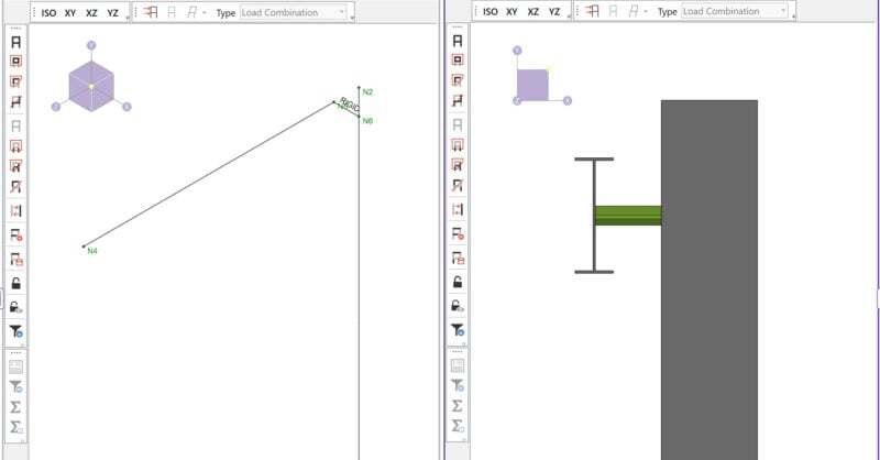
By default RISA-3D draws all members as line elements located at the centroid of the cross-section. However, connections between members are not...

Members (beams, columns, braces, etc.) are defined in RISA by an I-Node and a J-Node. While you and I see a beam occupying physical space...