Beam Deflection Ratio Options
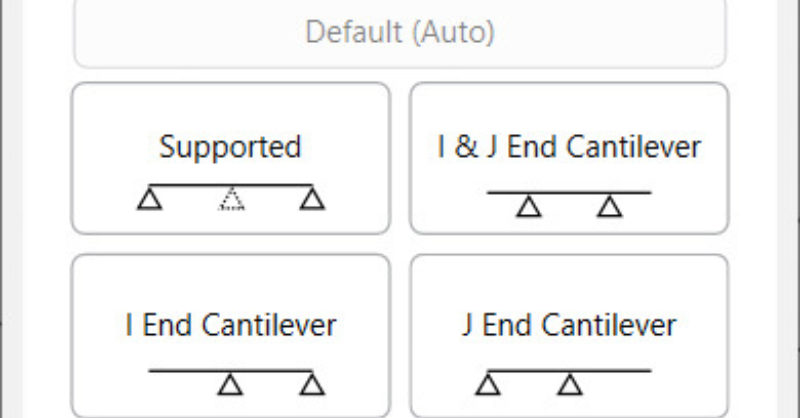
RISA-3D v16.0.4 introduces an enhancement that will allow for more control over the beam deflection ratio through Deflection Ratio Options. As...

Try the Complete RISA Suite for
10 Days FREE

RISA Education

Video Library

Online Help

Get Support

About Us
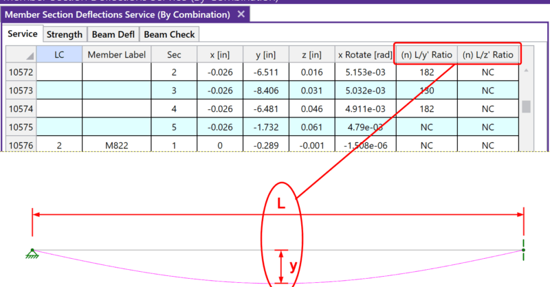
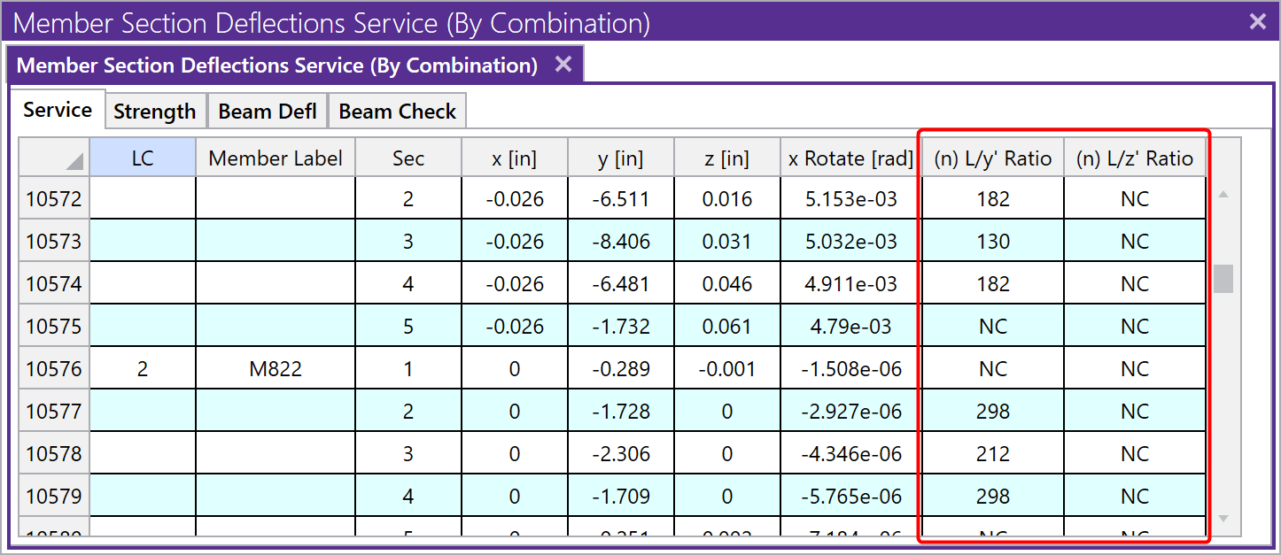
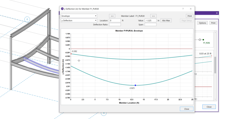
After solving a model, you will see in the Member Deflections spreadsheet the following deflection ratios:
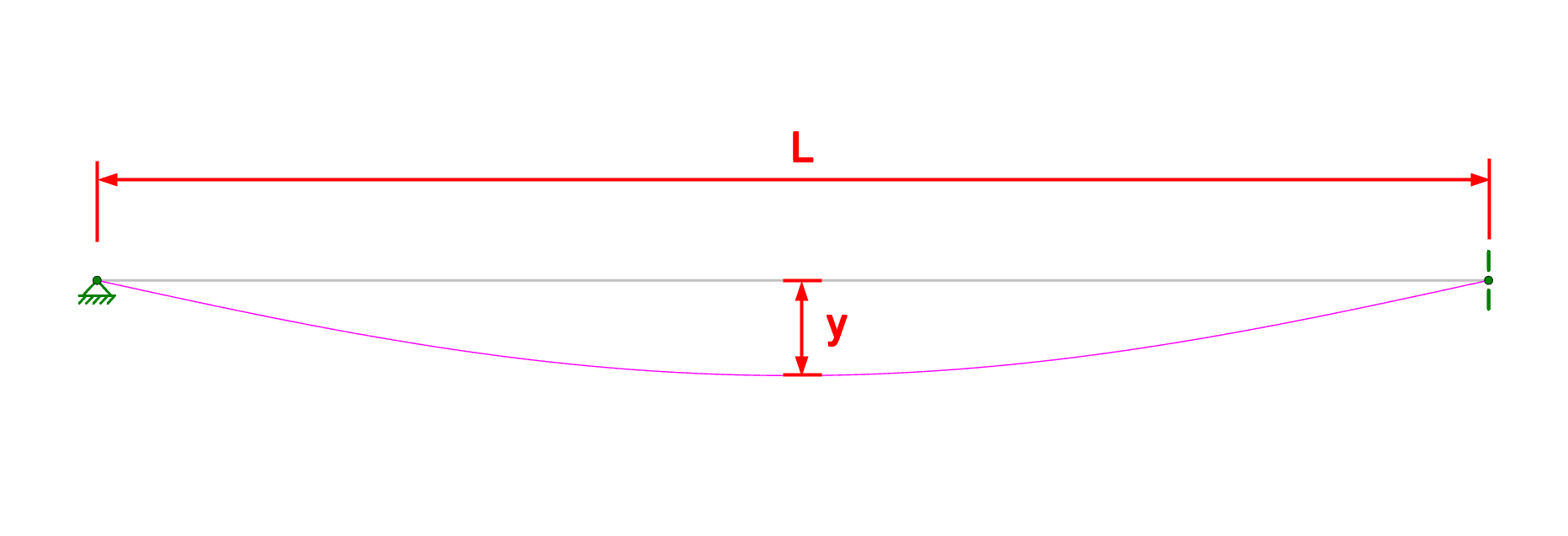
These ratios are calculated using the full length of the member (L) minus any member end offsets for a member supported at both ends. For member with a cantilever end or multiple spans, please search Beam Deflections in our Help File or see the linked Tips & Tricks article below for more information.
The variables y and z are the local y-axis and z-axis deflections relative to the straight line between the deflected positions of the end joints. For cantilevers the deflection is relative to the original position of the member.
Expressed as an equation, n = L/deflection, where n is what is tabulated in the spreadsheet above. The smaller the deflection, the larger the n value will be. If ‘NC’ is listed, that means the ‘n’ value is greater than 10000 which is a very small deflection. The minimum value that will be shown is ‘1’. For example, if the deflection criteria is L/360, check here to make sure no tabulated values are less than 360. Greater than 360 is sufficient.
RISA-3D v16.0.4 introduces an enhancement that will allow for more control over the beam deflection ratio through Deflection Ratio Options. As...
When solving a RISA-3D model with hot rolled steel members under the AISC 360-05 (13th Edition), AISC 360-10 (14th Edition) or AISC 360-16 (15th...
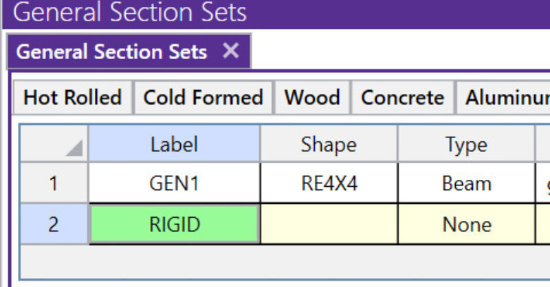
A rigid link is a member element in RISA-3D that can be used for many advanced modeling procedures. It is so useful that it is included as one of...