How to Add a New Pattern to the Moving Load Database
RISA-3D and RISA-2D come with a default list of existing moving load patterns. These are listed in the Moving Loads Library which can be viewed by...

Try the Complete RISA Suite for
10 Days FREE

RISA Education

Video Library

Online Help

Get Support

About Us

Using RISA-3D's various modeling and loading tools, makes modeling telecom structures easy and efficient. RISA-3D allows engineers to quickly explore numerous design variations before physical implementation.
When modeling the equipment dead load as a point load, have the point load applied at the center of mass of the equipment. However when the center of mass is not aligned with the pipe's, you can use one of two methods below:
Use rigid links to transfer the eccentric load
Apply a point moment load at the equipment support point due to eccentricity
If the pole centerline is different from the mount centerline and you want to capture this in the model, you will want to use rigid links. Follow the steps below:
Model in your structural pipe member
Then draw small rigid links that extend perpendicular from the pipe
Then place your loading at these rigid link locations so that the offset is captured. See an example of this below.

By default the program already has a rigid member set up for you within the section sets > general material. To use this member you can use the following settings when drawing your rigid links.

Link: Rigid Links in RISA-3D
If the pole centerline is different from the mount centerline and you want to capture this in the model, you can also apply moment loads directly at nodes. Calculate the moment load (M) by W x Rigid Link length (distance). Then follow the modeling steps below:
Model in your structural pipe member
Add nodes along the pipe member where the antenna attachment loads will occur. You can use the Node Coordinates spreadsheet or Add Nodes under the Modify tab.

Place moment point loads using Point Loads or Nodal Loads under the Home tab.


More Questions on Modeling for Telecom Structures? Reach out to our support engineers by clicking the button below.
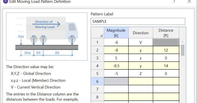
RISA-3D and RISA-2D come with a default list of existing moving load patterns. These are listed in the Moving Loads Library which can be viewed by...
When designing shear walls in RISA-3D, it’s common to add surface loads—whether to simulate lateral wind or seismic pressures, or even out-of-plane...
After solving a model with Member Area Loads, RISA-3D will automatically create Transient Basic Load Cases that allow the user to verify load...