 By: Admin
How are Unbraced Lengths coordinated between RISAFloor and RISA-3D?
In a RISAFloor model the columns and beams can be assigned unbraced lengths, or the program may calculate them automatically. This unbraced length...

Try the Complete RISA Suite for
10 Days FREE

RISA Education

Video Library

Online Help

Get Support

About Us
Understanding unbraced lengths and how RISA software accounts for them is essential in the design of any project. In RISA there are three main types of unbraced lengths:
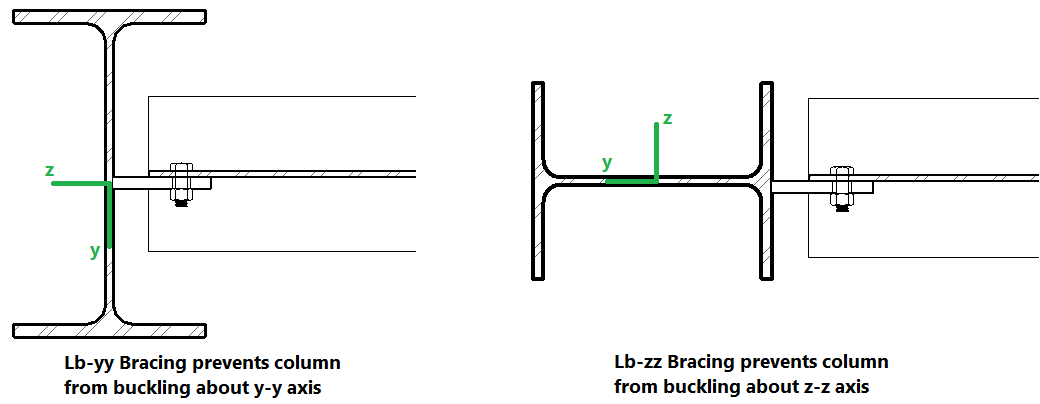
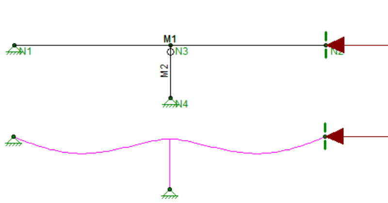
The Lb values (Lbyy and Lbzz) represent the distance between points which brace the member against flexural (column-type) Buckling about the member’s local y and z axes, respectively. Lb bracing prevents the entire member from moving laterally (perpendicular to its own axis). These Lb values are used to calculate slenderness ratios (KL/r) for both directions, which are used in the calculation of member axial compression capacity.
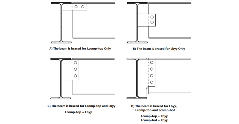
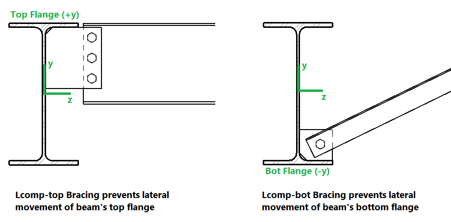
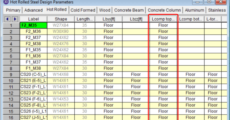
The Lcomp values (Lcomp-top and Lcomp-bot) represent the distance between points which brace the top or bottom flange of the member against Lateral-Torsional (beam-type) Buckling. These Lcomp values are used to calculate the member’s flexural (bending) capacity. Where the top flange of the member is in compression due to bending, Lcomp-top is used. Where the bottom flange of the member is in compression due to bending, Lcompbot is used. Lcomp bracing prevents the member’s flange from moving laterally (perpendicular to the member’s axis). The top flange is the flange on the positive local y-axis side of the member. Therefore if a beam if rotated 180 degrees about its own axis (flipped upside down) the “top” flange will actually be facing downwards.
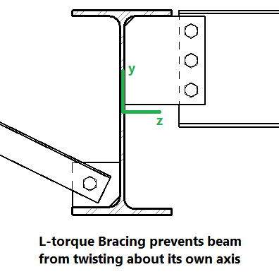
The L-torque value represents the distance between points which restrain the member against twisting about its own axis. This value is used to calculate the member’s Torsional Buckling and Flexural-Torsional Buckling capacity. These limit states affect the member’s axial compression capacity.
In a RISAFloor model the columns and beams can be assigned unbraced lengths, or the program may calculate them automatically. This unbraced length...

Aside from leaving an unbraced length blank or inputting a fixed distance, you can harness the program’s ability to use a limited intelligence for...
The axial compression and flexure strength of beams and columns is dependent on the spacing of elements which provide bracing along the length of...