


 By: RISA
Using Projected Loads in RISA-3D
RISA-3D, RISA-2D and RISAFloor have the capability to project...
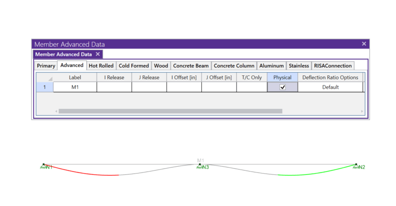
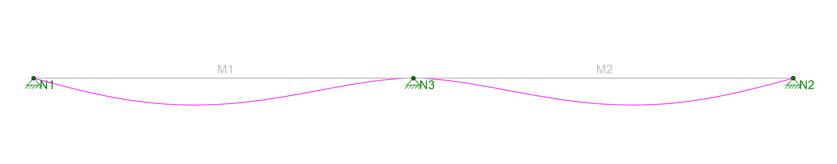
Members (beams, columns, braces, etc.) are defined in RISA by an I-Node and a J-Node. While you and I see a beam occupying physical space between two columns, most programs see a line between Point I and Point J. This is known as a non-physical member. See the image below:
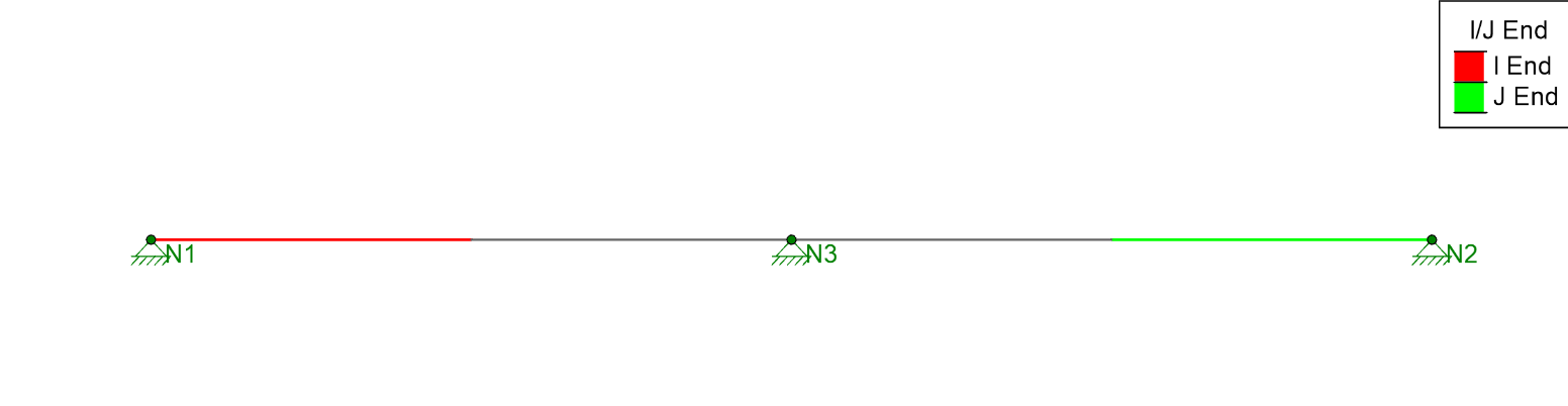
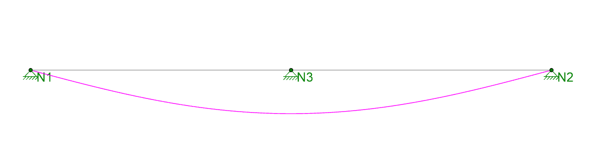
In this model the red side of the beam is the I-End (Node N1) and the blue side of the beam is the J-End (Node N2). There is clearly a midspan support, but this member is only defined with two joints, and it is not defined as “physical”, so the program is unaware that Node N3 is connected to the member. As a result, when the model is solved we get this deflection:
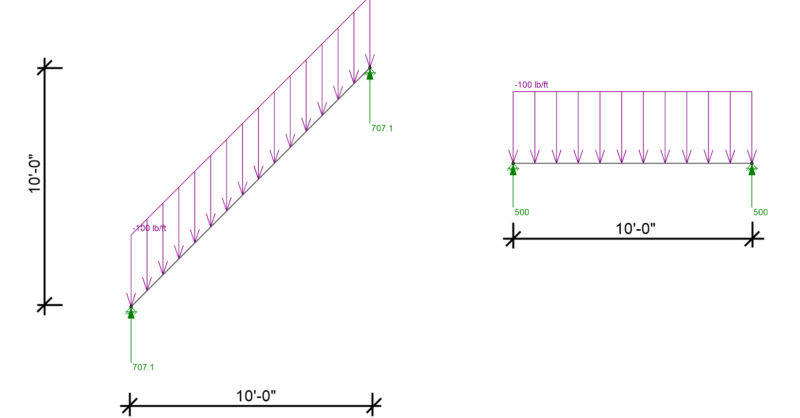
This has always been an issue for Finite Element Analysis programs which don’t support Physical Members. These programs recommend that you model the beam shown above as two beams:
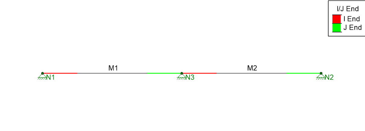
While splitting the beam into two will give you correct analytical results, it also means that you have twice as many results to sift through for one continuous member. Instead, RISA offers the ability to define the member as Physical, which means that it will recognize and automatically connect to any joint which falls along its length.
RISA-3D, RISA-2D and RISAFloor have the capability to project...
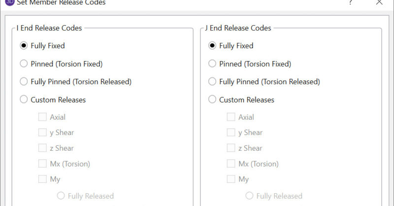
In RISA-3D, there are numerous options for Member End Releases which...

RISA has now incorporated the tapered member design provisions from...